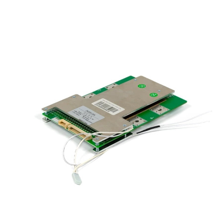
BMS 20s LiPo/LiIon - 120A/25A (symmetrical)
- Application: Battery 20s, LiPo/LiIon, Maximum continuous discharge current: 120A, Maximum charging current: 25A
BMS 20s LiPo/LiIon - 120A/25A (symmetrical)
Battery management system (BMS) - it is a device that automates the entire process of using batteries. After connecting a suitable charger to the BMS, it monitors its proper charging and discharging. It is an integral part of a properly constructed electric bike.
Lithium batteries (lithium ion, lithium polymer and others) are serviceable and require care and attention. They cannot be charged above 4.2V per cell and discharged below 3V per cell. In order to supervise them in everyday use, a device called BMS was invented.
TASKS PERFORMED BY BMS:
During charging, it balances and aligns individual sections so that they do not exceed the maximum safe voltage of 4.2V / cell. It automatically cuts off the charger if any of the cells are close to being reloaded.
During discharge, it makes sure that we do not discharge the battery too deep. In the event that any of the cells is already discharged - the BMS will cut off the power supply to the bike in order not to damage the batteries.
He tries to align the cells so that they always have the same voltage. This extends the service life and failure-free operation of the entire power supply.

The BMS is SYMMETRIC - it means that the charge and discharge field is common and is used to solder the charger cable -C and controller -P
The BMS has a service module - each of the balancer channels has a signaling diode informing about the activation of the balancing load on each of the channels. This allows you to check the condition of the batteries, informs about the weakest sections and helps diagnose any problems.
The BMS also has a turn-on circuit used to start the BMS after its installation in the target battery
Cabling is included with the BMS.
Connection description:
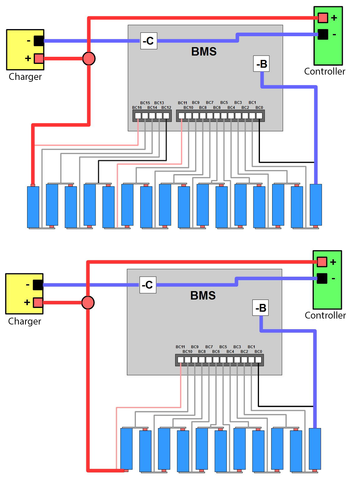
B- Connect the MINUS from the battery to this field
C- Connect the MINUS from the charger and MINUS from the controller to this field
Balancing Connector:
BC0- (from the right) is the first cell from the battery MINUS
BC1 (from the right) is the first PLUS cell and the second MINUS
...
BC5 (right) is the 5th PLUS cell and the 6th MINUS
...
BC9- ninth PLUS cell
...
BXX- (Last marking with the largest number) - Last battery cell (i.e. FIRST from plus)
Notes and Tips:
For proper operation, BMS requires an appropriate charger compatible with the battery operating voltage.
We recommend BMS assembly by people familiar with the subject of electronics / power. We suggest checking the correctness of connections 3x before the final start-up.
In an installation with a BMS, overcurrent circuit breakers, fuses and soft starters are not used. The BMS is not disconnected from the battery, it remains connected all the time.
The most common problems when connecting a BMS are confused and incorrectly soldered connectors to the cells: always check the connections 5x before connecting everything to the BMS. Draw everything on a piece of paper. Use a meter / multimeter. If in doubt, contact our technical department and study the connection diagram and descriptions available on the web.
The correct sequence of connecting the BMS:
1. Connect the battery cable (MINUS) to the appropriate field in the BMS -B
2. Connect the cable from the controller (MINUS) to the appropriate -C field
3. Connect the cable from the charger (MINUS) to the appropriate -C field
4. Connect the PLUS wires of the controller, battery and charger (it may spark slightly - this is normal)
5. Finally, connect the balancer cables to the balancer connector (make sure they are soldered in the correct order)
6. After completing the assembly, connect the charger for a while to activate and unlock the BMS at its first start-up.
You should avoid assembling the BMS cables in a different order, it may end up damaging them.
An exemplary connection diagram depending on the number of sections:

The store guarantees repair or replacement of equipment for up to 24 months for consumers and 12 months for companies from the date of purchase. Complete the complaint form available on the store's website.
What is not covered by the warranty?
- Errors in installation or maintenance
- Thermal damage (overheating)
- Modification/interference in the device casing
- Modifications/changes inside the device
- Mechanical damage caused by incorrect use of the product. e.g. damage from falls, excessive mechanical loads


